Valve Position Sensors for the Mk4 EVIC
 The Mk4 EVIC engine was designed to
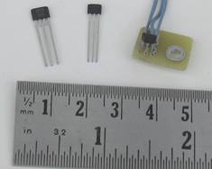
power a radio controlled model airplane. This 18cc engine now features chopper
stabilized linear Hall effect valve position sensors in the valve
solenoid assemblies. These sensors come in the small 3 pin SIP packages shown
here. The Mk4 uses Allegro A1374 programmable devices.
The Mk4 EVIC engine was designed to
power a radio controlled model airplane. This 18cc engine now features chopper
stabilized linear Hall effect valve position sensors in the valve
solenoid assemblies. These sensors come in the small 3 pin SIP packages shown
here. The Mk4 uses Allegro A1374 programmable devices.
I initially used these devices without programming, choosing instead to use them just as they come from the factory. Now I am programming them for mid sensitivity so that the signal from the sensors is at least 2 volts between the closed and fully open positions.
The engine controls have a Microchip PIC12F615 micro with a 10 bit A/D converter for each valve. These micro computers read the sensors and execute software to control valve motion.
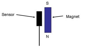 In order to achieve a linear valve position output the magnet in the
valve solenoid assembly lever arm is placed as shown so that the side of the
magnet slides past the sensor as the valve opens. The magnet must be long
enough to sense any valve overshoot that occurs on valve open and any lever arm
overshoot that occurs on close.
In order to achieve a linear valve position output the magnet in the
valve solenoid assembly lever arm is placed as shown so that the side of the
magnet slides past the sensor as the valve opens. The magnet must be long
enough to sense any valve overshoot that occurs on valve open and any lever arm
overshoot that occurs on close.
The Mk4 engine uses super magnets that are 2.5 mm in diameter by 5 mm long. They give the desired output range of approximately 2 volts between the valve closed and the fully open positions.
The magnets are positioned so that the sensor output is approximately 1 volt with the valve closed. This allows for close to 2 volts of valve open overshoot. The exact closed and fully open positions are not critical because the adaptive software is flexible enough to work with reasonable variations from these target values.
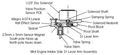 This drawing shows how the sensor and the magnet are
located in the engine’s valve solenoid assemblies. Note that the magnet is located
in the end of the non magnetic lever arm.
This drawing shows how the sensor and the magnet are
located in the engine’s valve solenoid assemblies. Note that the magnet is located
in the end of the non magnetic lever arm.
The valve lift is approximately 2 mm, 0.080 inches, and hence the magnet moves a little more than 2 mm between the valve closed and valve fully open positions. If the control is less than perfect the lever arm is free to move past the fully open and the closed positions. The 5 mm long magnet ensures that the position sensor output stays linear if overshoot occurs.
 With this arrangement both the lever arm and the
valve can overshoot the fully open position if too much solenoid force is
applied. However only the lever arm can overshoot the valve closed position if
the control provides insufficient close damping. The valve will be stopped by
the valve seat and if the close damping is insufficient it could bounce back
off the seat and perhaps be damaged.
With this arrangement both the lever arm and the
valve can overshoot the fully open position if too much solenoid force is
applied. However only the lever arm can overshoot the valve closed position if
the control provides insufficient close damping. The valve will be stopped by
the valve seat and if the close damping is insufficient it could bounce back
off the seat and perhaps be damaged.
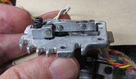
The photo shows the underside of the intake valve solenoid lever arm assembly with the sensor magnet and the sensor on the right.
Adaptive Control
Adaptive feedback control software controls the rate at which the valves open and close. For normal operation the software minimizes the overshoot on valve open and eliminates any valve bounce off the valve seat on close. The software also monitors the exhaust valve open response time and signals the main PIC16F628A micro to modify the exhaust valve table lookup based on the response time to improve performance.
Additional improvements to the control were made during the summer of 2011. The software now does a very good job of controlling the valves for my model airplane application. Better control for more demanding applications will likely require more sophisticated digital signal processing software.
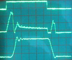 This photo shows oscilloscope waveforms of the intake valve open. The
time here is 2 milliseconds per division. The top trace is the valve open
signal. The middle trace is the solenoid current generated as a result of the
control outputs and the bottom trace is the output of the valve position
sensor. The valve lift is 2.1 mm, 0.083 inches. You can clearly see the time
it takes the solenoid to respond and the mild overshoot that occurs when the
valve reached the fully open position. You can also see how long it takes
after the open signal goes off until the valve starts to close. The current
pulse during closing provides damping so that the valve lands gently on the
valve seat with just a mild overshoot of the lever arm. Without the adaptive
feedback control an open overshoot of 2 divisions and a close overshoot of 1
division followed by the valve reopening a small amount were ocassionally
observed.
This photo shows oscilloscope waveforms of the intake valve open. The
time here is 2 milliseconds per division. The top trace is the valve open
signal. The middle trace is the solenoid current generated as a result of the
control outputs and the bottom trace is the output of the valve position
sensor. The valve lift is 2.1 mm, 0.083 inches. You can clearly see the time
it takes the solenoid to respond and the mild overshoot that occurs when the
valve reached the fully open position. You can also see how long it takes
after the open signal goes off until the valve starts to close. The current
pulse during closing provides damping so that the valve lands gently on the
valve seat with just a mild overshoot of the lever arm. Without the adaptive
feedback control an open overshoot of 2 divisions and a close overshoot of 1
division followed by the valve reopening a small amount were ocassionally
observed.
The improved control gave the engine more rpm when turning a 3 blade 14″ x 7″ propeller. Engine speeds in the air were approaching 9000 rpm. As a result I have now gone to a larger 3 blade 15″ x 7″ propeller because it provides more torque at lower rpm and holds the top speed down a few hundred rpm. Engine speed in the air still reached 8400 rpm during a flight on September 22, 2011.
The Mk4 plans in my EVIC book have been updated to show these latest improvements.
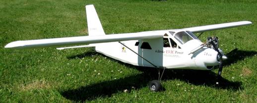
Ready to fly, July 1, 2011

Mk4 EVIC Flying my 8 foot (2.45 metre) wingspan Turbo Beaver, September 22, 2011
Last update - December 20, 2011