EVIC
Update #18 - October 1, 2003Experiments with my 2nd EVIC -111 Single
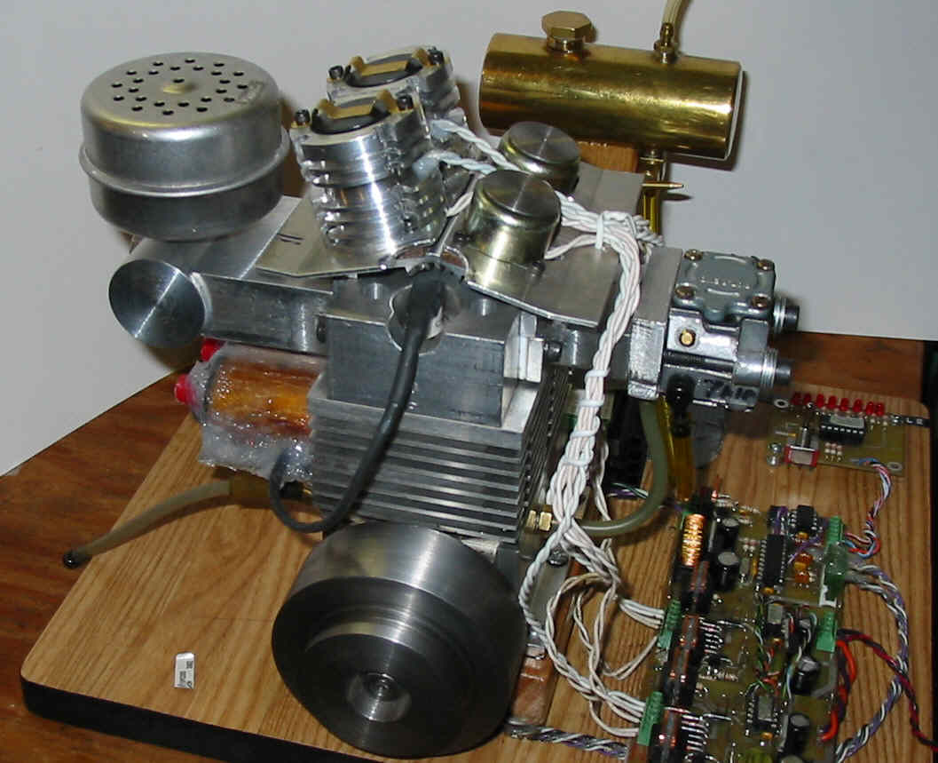
This engine was back in my 52" Deep V radio controlled boat in May. It ran very well on May 29th. There is a video posted in the files section of the Yahoo EVIC Group. See the address at the end of this Update. Because the engine now has more power it is driving an Octura X465 prop, one size larger than the X462 I used last year. On May 29th the engine was running with 2 ganged solenoids on the exhaust valve, a Bicron SP2515P0300 and a solenoid with a flat solenoid that I built myself above it. The intake was still operated by a single Bicron SP2515P0300 solenoid.
My latest power measurements, made in May by driving a Delco alternator, indicate that this engine is producing just under 0.4 hp at 8000 RPM. I wanted more performance.
Compression Tests
I made a 10mm adapter for an automotive compression tester. Tests with this meter indicated an 8.5:1 compression ratio. My calculations give 10.5:1. As a result I tried making new compression rings with a smaller (0.002") end gap. I used Bob Shores' method (see http://www.floridaame.org and select Tips and Links, Tip #6) and spread the rings 0.125". The results were worse, 7:1. Examination under magnification showed a slight gap in the area where the rings were heated. I have found that Bob's method works well when I limit the spread to 1/16" but I wanted more cylinder wall pressure. I made another set of compression rings. This time I spread the rings the same amount, 0.125", but I clamped each ring between 2 washers before heating the washers and the entire ring. These rings look perfect under 8 power magnification. When tested the compression ratio read 8.5:1, the same as with the original rings. Adding a few drops of oil to the cylinder results in a reading of 9.5:1. This indicates there is still some leakage around the rings. I also think that the meter has trouble giving accurate readings with my small 12.5cc cylinder volume and as a result is reading low. Has anyone had success doing compression tests on small cylinders?
A 2nd Intake Valve Solenoid
During the summer I added a second solenoid on the intake valve. This is a flat faced solenoid identical to the second one on the exhaust valve. I increased the intake valve lift. I replaced the valve spring with a stronger one that generates 3lb 2oz of force. With the ganged solenoids I increased the valve lift to 0.060" and still managed to get this valve to both open and close faster than before. I tried higher lifts but this slowed both the opening and closing. The unloaded top speed with this configuration was ~ 11,000 RPM
I experimented with several different flat faced top solenoids on the exhaust valve in an attempt to get this valve to operate faster and to get more lift. I changed the exhaust valve spring to one giving 3lb 2oz of force. The result of the spring change is that the exhaust valve closes faster. I ended these experiments by going back to solenoids I started with. I didn't make any gains in opening speed or lift. With each change I checked the unloaded top speed and the performance in the boat. The unloaded top speed crept up to about 11,500 RPM with the stronger valve spring but the performance gains in the boat were modest at best.
I decided that my inability to improve performance was a result of limits in the software. I tried a number of changes in an attempt to improve the software. None made any measurable difference.
I am beginning to wonder if I am not expecting too much from a 12.5 cc 4-stroke engine. (The boat was designed for a 23 to 25 cc 2-stroke engine.)
Recently I tried running the engine without the muffler. This gave some interesting results. The "Electronic Throttle" did not work. The top speed increased as the valve timing was changed to throttle the engine. With the "ET" set to idle the speed was just a few hundred RPM below the full throttle value. Besides changing the intake valve timing the "ET" uses late exhaust valve closing when throttling the engine. The exhaust back pressure results in some exhaust gas re-circulation. Without any back pressure the "ET" effectiveness is reduced. Without the muffler I expected the idle speed to increase to perhaps 3500 to 4000 RPM. I didn't expect 9000! Nor did I expect the engine to turn 12,200 RPM at about 1/2 throttle! My conclusion is that the muffler is giving too much back pressure. I tried increasing the size of the exhaust outlet and this did result in a small increase in the top speed with the muffler installed. I plan to investigate further. Does anyone have any tips on muffler size and selection for small 4-stroke engines? Muffler volume? Exhaust outlet size? Do any of the 2-stroke techniques (tuned pipes) work on 4-stroke engines?
Mechanical Problems
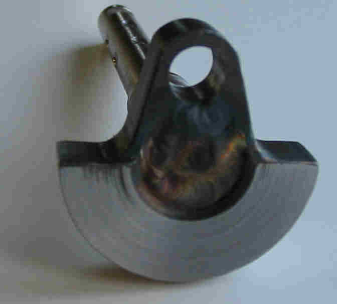
I had mechanical problems with the engine during the summer. The pin installed to keep the crank disk from rotating on the crankshaft worked loose and caused some minor damage. I replaced the pin and "riveted" over the opening so that it "could never come out again". I also added a setscrew that went right into the shaft to try to make sure that the disk could not move on the shaft. These changes held the engine together for the month of August. Then, after a bench test to try some software changes, the pin came out and the disk slipped about 80 degrees around the shaft. This time there was more damage to the rod and the crank pin was bent down slightly.
Last year you will recall that I reduced the diameter of the crank pin to 0.250" and squeezed a B47 roller bearing into the big end of the existing connecting rod. This configuration lasted nearly a year. I believe the 0.250" crank pin wasn't strong enough and bent under the increasing load that resulted from my attempts to increase engine power. I think the bent pin put additional stress on the crankshaft and this stress led to the crankshaft problems.
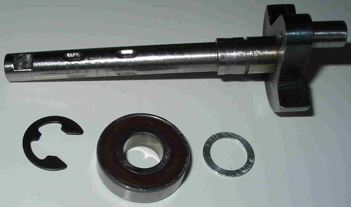
I decided replace both the crankshaft and the rod. I made a stronger crankshaft with a larger bearing inside the engine, a 6001 with a 12mm ID (0.472"). The shaft reduces to 0.375" just before the outside bearing. I press fit the parts together as before and then had the disk TIG welded to the end of the shaft. I couldn't resist making the stroke a few thou longer to increase the compression ratio to 11:1!
I added an E ring to the crankshaft to prevent the bearing from sliding along the shaft. I had this problem with the old shaft. Perhaps it moved because the crank pin was bent. This one isn't going to move! I used Permatex (Loctite) High Temperature Sleeve Retainer to ensure that the bearing OD stays fixed in the bearing pocket in the crankcase.
The new rod has an HK0810A roller bearing on the big end and the crank pin is 0.315" (8mm). (The original design calls for a 5/16" crank pin.) I used a B47 roller bearing on the little end. To save weight I made the rod proper 0.220" thick instead of 0.250". Performance was back to normal with the first runs with this new configuration on September 29th. Now I am back to looking for a better muffler.
The EVIC Twin
I delayed work on my EVIC Twin while I did the solenoid experiments described above on my 2nd single. Then I completed the Twin. It now has dual exhaust valve solenoids and a Briggs & Stratton lawn mower muffler like the one on my 1st single. The engine is runnig well even though I haven't replaced the crankshaft with the 8 thou wobble. As reported in Update 17, this is a result of an error that slipped in while I was making the crankshaft pieces. The new crankshaft will be stronger and get 6001 bearings. I have had the Twin up to 10,000 RPM. I had expected excessive vibration with the crankshaft wobble but, although it vibrates, the vibration doesn't seem to be excessive. An EVIC Twin book is in the planning stages. My current thinking is that it should be available in time for Cabin Fever 2004.
Ignition System Improvements
Initially I tried a single coil firing both plugs at the same time on the Twin. I had problems with this system so I went to 2 coils to avoid the use of a distributor. During the summer I had some problems starting my 2nd single. I traced this down to a lack of spark when cranking the engine. If it started it seemed to run properly. I took a closer look at the ignition circuit. I have been using a 100 volt power MOSFET to switch the coil current. When the coil current is switched off, the voltage on both sides of the coil increases until the spark occurs on the secondary (HV) side. Under some conditions the voltage on the primary (low voltage) side was exceeding the break down voltage of the MOSFET. When this happens, energy intended to go into the spark is lost on the primary side of the coil. The problem gets worse with a higher compression ratio, if the spark plug is fouled and with some weather conditions (high humidity). I tried higher voltage devices, both IGBTs and 200 volt MOSFETs. Both worked much better. I am currently using a 375 volt IGBT on the single and 200 volt MOSFETs on the Twin. The 200 volt IRF9640 MOSFET is a direct replacement for the 100 volt device used on all my Electronic Packages. I will supply a replacement device to anyone having an ignition problem. Contact my by E-mail.
Electronic Fuel Metering - EFM
 ---
--- 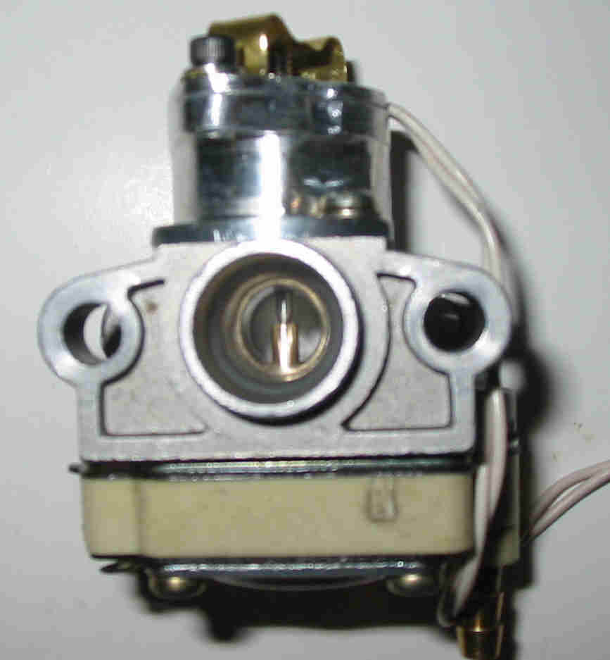
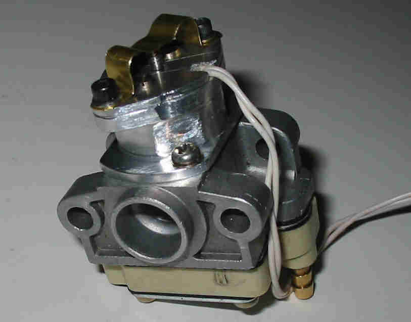
I have started work on a fuel metering system. I won't call it fuel injection because the fuel pressure will be low, 6 to 8 psi. The first prototype is based on a Walbro WYL carburetor. I selected this model because the crankcase pressure operated fuel pump is located on the bottom of the carburetor. (It is split top and bottom on most of the Walbro carbs.) I have completed all the new parts and assembled them on top of the carburetor as shown above. I expect to start tests in a week or 2 after I get the electronics and some software together. Fuel flow will be controlled by pulse width modulation. Initially I will keep the electronics separate from the engine control. This will allow EFM to be added to existing engines without the need to buy new engine control electronics. If it works well I integrate the control into the next version of the EVIC Electronics Package.
The EVIC Group on Yahoo
Back in January Dirk Tollenaar started an EVIC group on Yahoo.
http://groups.yahoo.com/group/EVIC-111/
After a slow summer, activity on this group is increasing. I recently added a message correcting an error in my book and I added more pictures. I will continue to support this site and I encourage all EVIC builders to do the same.
Dave Bowes