EVIC
Update #13, April 23, 20022nd EVIC Running with a Top Speed over 10,000 rpm
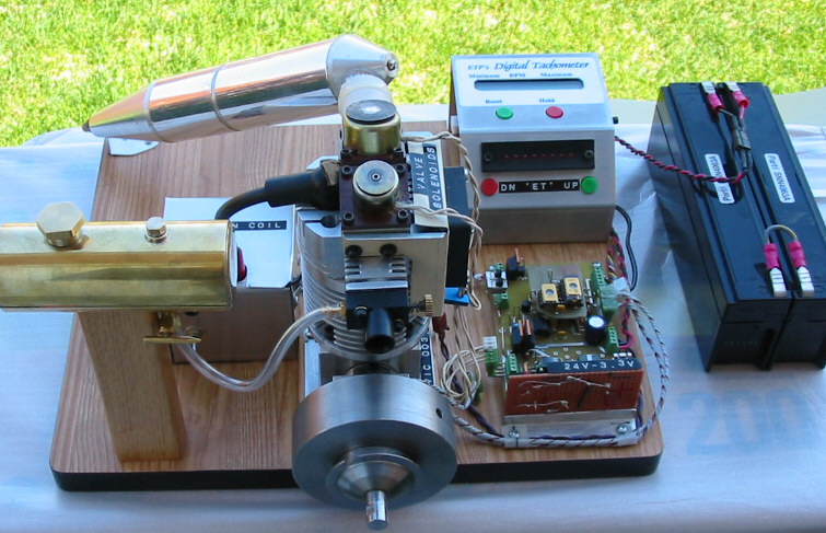
After reaching 10,000 rpm with my first EVIC engine in March, I decided it was time to complete my second engine. My goal was (and is) to show both engines at NAMES. The new head came off the first engine and became, as intended, the head for my second engine. This new EVIC has a one piece all aluminum crankcase making it quite a bit lighter than the first. The bore is still 1" but I made the stroke on this one 0.9375". The compression ratio is higher, 9:1 vs 7:1. The cylinder liner is cast iron instead of steel. The flywheel is the same weight but slightly larger in diameter giving it 25% more inertia.
The improvements in the head were documented in Update #12 and allowed me to get the first engine to run over 10,000 rpm. (Lighter valves, bigger intake than exhaust, etc.). I have a Revolution model airplane muffler (quiet, semi-tuned pipe) on this engine. The carburetor doesn't have a throttle barrel so the only way the engine can be "throttled" is by changing the valve timing or by running it in the Hit & Miss mode.
I ran this new engine for the first time on April 5th. For the first tests I used the electronics, ignition coil, muffler and fuel tank from the first engine. After a few adjustments to the valve springs and valve lifts I recorded a top speed of 10,400 rpm on April 7th. By this time I was using the semi-tuned pipe model airplane muffler. Then I started working on the electronics for this new engine.
I had planned on using a PIC16F628 micro for this engine but I am not there yet. Instead I decided to modify one of my existing control boards and then go the new micro as a second step. I changed the solenoid drive circuits to eliminate the power resistors that create the holding voltage used to keep the valves open. The new circuit uses a DC-DC converter with a 3.3 volt output to create the holding voltage. Because I used an off the shelf part this adds about $50.00 to the electronics cost. However it has the advantages of high efficiency and it will allow me to experiment with higher voltages to force the valves to open without having to make other circuit changes. It also allowed me to remove the steering diodes from the high voltage (high current) path and thus gain a little move solenoid force with the 24 volt control battery. The steering diodes are now in the holding voltage circuit and drop the 3.3 volts down to the desired 2.6 volt holding voltage. The exhaust valve circuit is shown below:
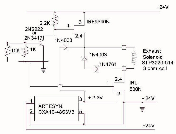
As a result of these changes I was able to increase the valve lifts to 0.035". This is a significant improvement over the 0.028" lifts I had with this new head and the old electronics. As the valve lift is increased the engine's mid range power output improves but the valves are more likely to float at high speed. Stronger springs will eliminate valve float but with stronger springs more solenoid power is required. My goal is now to increase power output without loosing top end speed.
With the modified electronics I again experienced EMI problems caused by the ignition spark. The resulting glitches in the engine control were greatly reduced by shielding the ignition coil. I strongly recommend than anyone building the engine shield the coil. I enclosed mine in a box made from aluminum sheet and grounded this box to the engine's crankcase. I also shielded the leads coming from the control board to the coil, connecting the shield to the box surrounding the coil. I think that using resistance wire for the high voltage lead to the plug might be a good idea but I haven't tried this yet. I haven't tried putting the control electronics inside a shield but this may be my next step. I have resisted doing this because I like having easy access to the electronics for monitoring the circuits with a scope.
The "Electronic Throttle", "ET", does not work as well on the new engine as it did on my first engine. The improved head breathes better and as a result the new engine only slows down to around 3200 to 3400 rpm with the shortest intake valve open time I can achieve with the new solenoid control circuit and the new valve assembly. I have resorted to Hit & Miss operation to achieve lower speeds. This gets the "idle" speed down to about 1800 rpm. I plan to try some control changes along with a stronger intake valve spring to get the valve to close more quickly and hence extend the "ET" range. If time permits I will try a few experiments before NAMES.
During the course of my experiments I discovered that the 78L05 voltage regulator used on my control board (and shown in my book and the Strictly I.C. schematics) is badly overloaded when the control board powers the "ET" Controller. To solve this problem the 78L05 (TO-92 package) must be replaced with a 7805 (TO-220 package). If you don't use the optional "ET" Controller the 78L05 should work okay but it is on the edge and any attempt to increase the control voltage beyond 24 volts may cause the 78L05 to go into thermal shutdown. The 78L05 may get hot but nothing should be permanently damaged. To ensure reliable operation I recommend changing the 78L05 to a 7805. All my new boards will have the 7805. I have also modified the "ET" controller design to reduce its power consumption. If you are building or have built one contact me for the latest schematic.
There will be 3 EVIC engines at NAMES this year. My 1st engine will be in the original configuration as presented in Strictly I.C. and my 2nd engine will be as described above. Bob Heide will also have his EVIC there giving you the opportunity to see 3 working examples of this exciting technology.
Dave Bowes