EVIC
Update #12, March 6, 200210,000 RPM!
Today I achieved the goal I set back in October; 10,000+ RPM.
Top speed today was
10,714 RPM.New Cylinder Head
Back in January I decided to make a new cylinder head to incorporate all the things I have learned from the books by Lumley and Lichty. Here is what I did:
1. I reduced the diameter of the exhaust valve to 0.380" and increased the intake to 0.425". They were both 0.400".
2. I moved the spark plug over a few thou, enough that I could move the valves 0.100" toward the center of the head. This allowed the valves to be further apart and further from the cylinder walls as Lumley suggests.
3. After reading Lichty I decided to make the valve seat angle 30 degrees. This should allow a bit more flow for the same valve lift.
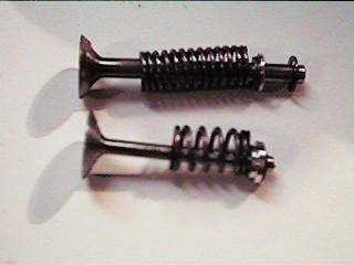
4. I made the valve stems 3/32" instead of 1/8" in diameter. This cut the weight of the valves almost in half, from 4 grams to just over 2. The photo shows an old valve above the new intake valve.
5. I made the valve springs from 7 turns of 0.032" music wire. The intake spring force is 16 ounces, the exhaust 20 ounces when the valves are closed.
6. I mechanically limited the valve lift to 0.070" so that the valves can't overshoot beyond this if they are opened very quickly by the solenoids.
7. I raised the manifold passages up in the head by 1/16" so that I could better round off the transition from the horizontal passages to the 75 degree valves.
8. I made the horizontal manifold passages larger, 3/8" instead of 11/32".
9. I shaped the combustion chamber to encourage flow from the intake valve toward the spark plug rather than out the exhaust valve.
The solenoid mounting bracket is similar to the one I made in October. See update #11 on the web. The return springs that keep the solenoid armatures from overshooting when the valves close are located under the solenoids. The lift adjustment is with plastic adjusters similar but more compact than on the original design. The solenoids are the same Bicron units I have been using since day one. The armatures have been modified to reduce their weight.
All of the changes are aimed at achieving two goals:
The March 5 & 6 Tests
The new head was installed yesterday, March 5. It took 4 runs to sort out a few bugs. It was obvious from the start that this head is a better design. The top speed increased on each run. It easily ran up over 9000 RPM on the second run and then to 9590 on the third. The exhaust valve lift dropped on the 4th run because the valve stem started to pound a hole in the Teflon lift adjuster. I made a new one out of a harder plastic for the next test and that did the trick. Within seconds of starting the speed reached 9800 RPM. I throttled back to idle and the engine stalled. After restarting and adjusting the mixture I watched as the top speed climbed to 10,013 RPM. Fiddling with the needle valve and stepping the "Electronic Throttle" down and up a couple of steps produced peak readings of 10,107, 10,135, 10,316, 10,390, 10,606 and finally 10,714 RPM!!! I was very happy.
Design Issues
The new design isn't quite "production" ready yet. The exhaust valve stem got hot enough to melt the plastic lift adjuster. The solenoids got very hot. The 220uf capacitor in the exhaust solenoid circuit overheated and will likely fail. The "Electronic Throttle" needs to be reworked because the idle speed is now over 3000 RPM. And finally the tin plating was melting off the muffler!
Next Steps
Drawings have been made for the new head, valves, valve springs and the solenoid mounting bracket. I still have to complete the new drawing for the solenoid modifications and the valve adjusters. I have to come up with a satisfactory valve adjuster and then determine the optimum valve lifts for this new head. This will require several design iterations involving changes to the lookup tables in the micro. Heat sinks can be added to the solenoids if required. A capacitor with lower ESR will solve the problem with the 220uf cap. Maintaining a 10,000+ RPM top speed and getting the idle speed down will require changes to the "ET" software and perhaps a change to the carburetor to keep the mixture from getting lean at low speed. I expect to have all this sorted out before NAMES.
3 Hit & Miss Speeds and a H&M Idle Speed Regulator
After Cabin Fever I added a 3rd Hit and Miss speed to the control. The new speed is 1450 RPM. I selected this speed because I wanted to use the Hit and Miss function to regulate the idle speed. Sometimes, when the carburetor is leaned out for the best possible top speed, the "ET" gives an idle around 2000 RPM. Since I want a 1450 RPM idle I added a control loop to Miss if the "ET" is set for idle and the speed is above 1450 RPM. This logic works quite well and brings the idle speed down. However the speed can drop as low as 1200 RPM and when the engine Hits (just one hit) the speed jumps to about 1650 RPM. Although this is an improvement I hope to make a better idle speed regulator in the future.
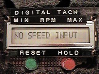
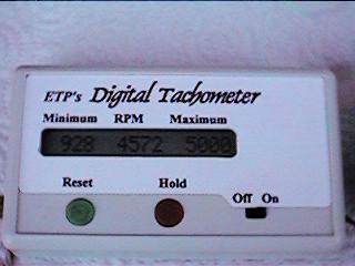
Digital Tach Allows Accurate Speed Measurements
Throughout this update I have been giving lots of info on engine speed. That's because I developed a Digital Tach in January that displays the current engine RPM and also records and displays the minimum RPM and the maximum RPM. This device has made my testing much easier. Because the clock for the micro in the tach is crystal controlled the tach has an accuracy of better than ± 5 RPM. A 16 character LCD display lets me view all 3 values at one time. I got such a positive response from the folks who saw my two prototypes at Cabin Fever that I decided to build a bunch and offer them for sale. Two versions are shown in the photos, the first one I use for my EVIC tests and the 2nd one packaged in a case. Tach details can be found on this web site.
Dave Bowes