In Update #8 I told you about my "valve problem", a problem where I thought the intake valve was leaking when the engine heated up. Although I did have a small problem with the intake valve it turns out that the real problem was vapor lock. Dave Bray, a member of Toronto Society of Model Engineers, asked me if I had considered this when I was demonstrating the engine at a club function in June. That prompted me to read up on the subject and then try a heat resistant plastic spacer between the cylinder
head and the carburetor. Problem solved! The fuel was essentially boiling in the carburetor. The plastic provided enough insulation to drop the carburetor temperature to below the gasoline's vapor point.
Having solved this problem I moved on to see if I could extend the speed range of the "Electronic Throttle" and increase the engine's power output. I tried measuring power first using a DC motor as a generator and then a car alternator. I was having difficulty getting the alternator to run at more than one speed for long enough to get a power measurement when, in early August, I saw a picture of a dynamometer being used to test a model engine in the October 2001 issue of Radio Control Boat Modeler.
With the help of the magazine staff I was able to contact Mike Hoffmeister, the author of the article, via E-mail. He pointed me to these two web sites:
http://www1.cedar-rapids.net/tdkmotor/
http://home.sprintmail.com/~mikejhoff/dyno.htm
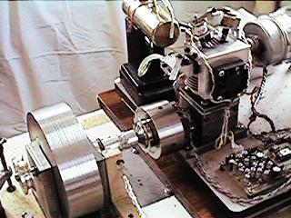
These sites have a wealth of information on how to build and use an inertia dynamometer. I built one with an 8 pound flywheel to test my EVIC engine. See picture. Note the cooling fan I mount on the engine when doing these tests. I pulled out my old 80286 computer and an INS8073 micro from 15 years ago to construct my own data gathering system. My first tests showed unusual torque and horsepower curves. Even though I could get the engine to run up to 7000 RPM my tests showed that I had very little power above 3000 RPM and the engine would only accelerate the flywheel to a little over 4000 RPM. On top of this my "Electronic Throttle" wouldn't work if the engine's speed got over 6200 RPM. It just didn't slow down when the valve timing was changed. A few more tests and a little head scratching convinced me that stronger valve springs were required. The lack of power was because the valves were closing too slowly. The "Electronic Throttle" was failing because the intake valve was being sucked open at high speed. I began making stronger intake valve springs switching from 0.020" to 0.025" and then to 0.032" music wire. Each time I made a new spring I measured the force required to compress it to 9/16" long. I went all the way from a 6oz spring to a 28oz intake valve spring. With a 10oz spring the engine's power increased in the 3000 to 4500 RPM range and the "Electronic Throttle" worked to nearly 7000 RPM. With a 28oz spring I had to cut the valve lift in half to a mere 0.015". The intake valve solenoid doesn't have enough power for a greater lift with this spring. Also there was a significant drop in top speed. The best compromise appears to be an 18oz spring with a 0.020" lift. I also changed from a 10oz to a 15oz exhaust valve spring. After revising the lookup tables in the software to match the new springs I was able to tune the "Electronic Throttle" to give a speed range from 1400 to 7000+ RPM. With these changes the engine accelerates the dynamometer's flywheel to 6000 RPM. The torque curve still has some odd peaks the most noticeable one being just above 2000 RPM. I believe they are caused by resonances in the valve assembly. I plan to try a more compact assembly with less mass. I will reduce the valve springs from 14 turns to 7 and reduce the height of the engine by a half inch.
My wife Lynne and I traveled to Eugene, OR in September to attend the PRIME show. We were guests at the Strictly I.C. booth and I must say that Bob and Frances Washburn treated us very well. I ran my engine what seemed like a thousand times without any problems. I also picked up an additional 23 names to add to the EVIC Interest Group for a total of 87.
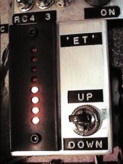
Just before the show I built an "Electronic Throttle" Controller with a center off DPDT switch to increase or decrease the speed. It has 8 LEDs to indicate the "ET" setting. See picture. It used a PIC16C505 micro in the controller and makes the engine look a bit more high tech. Since this won't be in the final issue of Strictly I.C. I will supply the schematic and software for this controller via E-mail to anyone who is building the engine. A programmed PIC is available for US$10 including postage.
 -
- 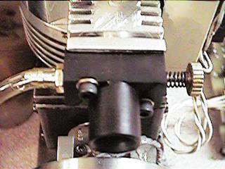
Since returning from PRIME I made another carburetor, the third, for the engine. See picture. This one doesn't have a throttle drum so when it is mounted the only way to control the engine is via the "Electronic Throttle". I made the body in two pieces. The piece that holds the spray bar and needle valve is made from plastic to prevent vapor lock. Unfortunately the plastic expands so much with temperature that the needle valve setting changes considerably as the engine warms up. So I reverted to another plastic spacer between the carburetor and the cylinder head to solve this problem.
My current goal is to get my engine's top speed to 10,000 RPM. I am inching my way toward that goal and yesterday got over 9000 RPM for the first time. More on this in Update #11.
Dave Bowes
EVIC home page